
Oneshape Featurescript
How to import testpoints from PCB into Oneshape using some FeatureScript.
Prepare testpoints
The first step we have to change the Fabrication property for each testpoint.
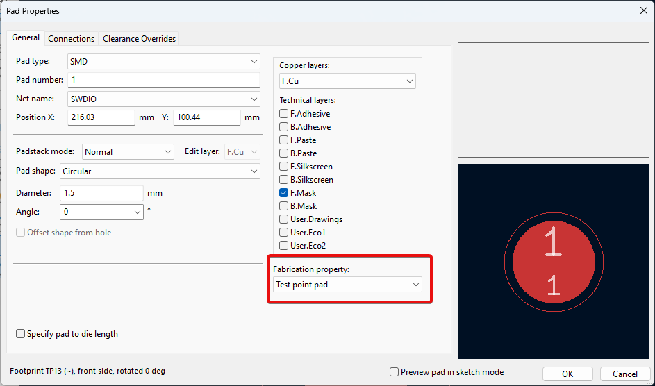 It is super annoying to make it one by one, so you can change only one and apply to other automatically.
Right click -> Push Pad Properties to Other Pads
It is super annoying to make it one by one, so you can change only one and apply to other automatically.
Right click -> Push Pad Properties to Other Pads
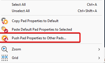
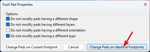
Done, all identical test points should have the Fabrication property changed. If you have different test points you have to do it for each type.
Testpoint report
I’m using plugin “Testpoint Report Setup”.
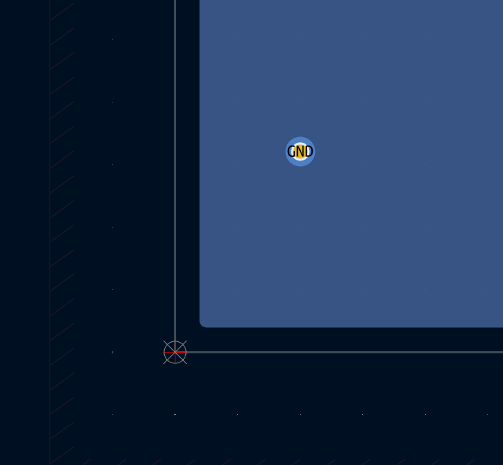
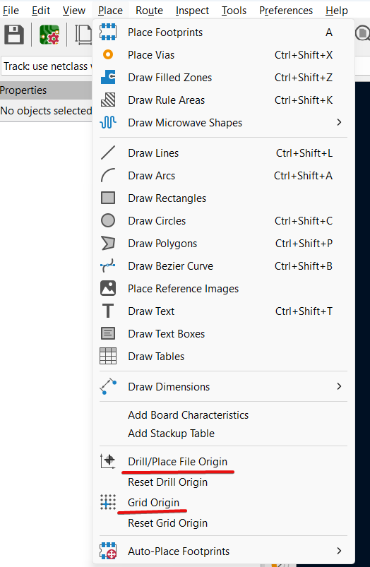
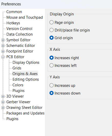
We need the coordinate system to start from the bottom left corner, so testpoint positions will be calculated from this point. And it will be much easier to position our PCB in 3D view by two edges.
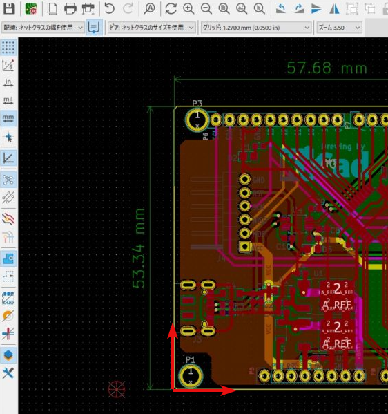
The origing should be selected as the bottom left crner of the PCB
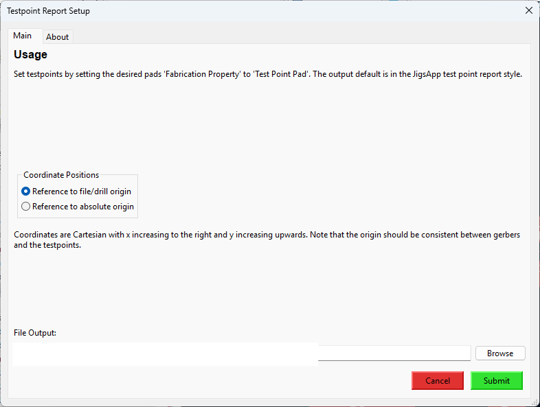
After submitting you can see the .csv file created.
Import data into OneShape
All this I needed to have the holes imported into one shape automatically. We can import position of each testpoint as point from file to our sketch using Feature studio.
Feature Studio in Onshape is a powerful, built-in scripting environment that allows users to create custom features using a programming language called FeatureScript. It’s designed for advanced users who want to go beyond the standard modeling tools provided in Onshape.
First think is that all values from .csv file are in mm.
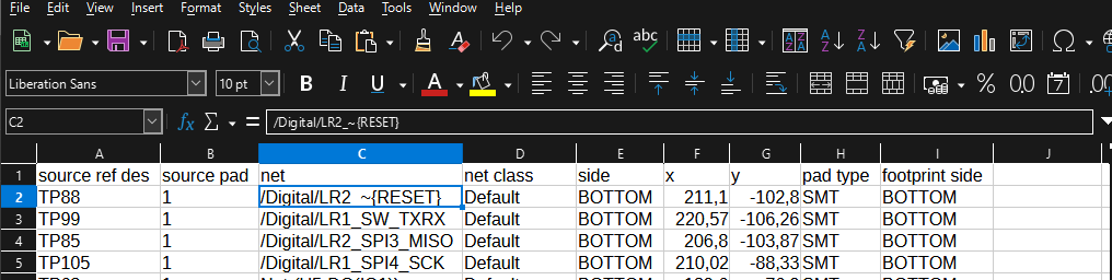
If we open the .csv file using Notepad, we will see something like this
"source ref des","source pad","net","net class","side","x","y","pad type","footprint side"
"TP88","1","/Digital/LR2_~{RESET}","Default","BOTTOM",211.1,-102.8,"SMT","BOTTOM"
"TP99","1","/Digital/LR1_SW_TXRX","Default","BOTTOM",220.57,-106.26,"SMT","BOTTOM"
Looks kind of different as from excel, but it is what it is.
so, we need the numbers, which is located in 5 and 6 column, the first one is x, and second is y.
I have found the script here , and modified it for my needs
FeatureScript 2679;
import(path : "onshape/std/common.fs", version : "2679.0");

 const MY_HOLES_DIAMETER =
 {
      (meter)      : [-500, 0.00135, 500],
      (centimeter) : .135,
      (millimeter) : 1.350,
      (inch)       : 0.053,
      (foot)       : 0.004429134,
      (yard)       : 0.0025
  } as LengthBoundSpec;

const TP_X_COLUMN = 5;
const TP_Y_COLUMN = 6;
const PCB_SIDE_COLUMN = 8;

annotation { "Feature Type Name" : "KiCAD CSV" }

export const xyzCSV = defineFeature(function(context is Context, id is Id, definition is map)
    precondition
    {
        annotation { "Name" : "Table" }
        definition.pointData is TableData;

        annotation { "Name" : "Plot TOP",  }
        definition.bPlotPointsT is boolean;

        annotation { "Name" : "Plot BOTTOM",  }
        definition.bPlotPointsB is boolean;

        if (definition.bPlotPointsT || definition.bPlotPointsB)
        {
            annotation { "Name" : "Cut",  }
            definition.bCut is boolean;

            annotation { "Name" : "Holes Diameter" }
            isLength(definition.holeDiameter, MY_HOLES_DIAMETER);

            annotation { "Name" : "Start Point", "Filter" : EntityType.VERTEX  , "MaxNumberOfPicks" : 1 }
            definition.orig is Query;
            annotation { "Name" : "End Point", "Filter" : EntityType.VERTEX  , "MaxNumberOfPicks" : 1 }
            definition.origend is Query;

            annotation { "Name" : "Choose face", "Filter" : EntityType.FACE, "MaxNumberOfPicks" : 1 }
            definition.face is Query;

        }
    }

    //---------------

    {
        var importedData = definition.pointData.csvData;
        var numRows = size(importedData);
        var points = [];

        println("Value of numRows: " ~ numRows);

        var cx = TP_X_COLUMN;
        var cy = TP_Y_COLUMN;

        // create coordinate system
        var startPosition is Vector = evVertexPoint(context, {
                "vertex" : definition.orig
        });
        var endPosition is Vector = evVertexPoint(context, {
                "vertex" : definition.origend
        });

        var xDirection is Vector = normalize(endPosition - startPosition);
        var zDirection is Vector = evOwnerSketchPlane(context, {
                "entity" : definition.face
            }).normal;
        var cSys is CoordSystem = coordSystem(startPosition, xDirection, zDirection);


        // create scetch plane
        var sketchPlane is Plane = plane(cSys);
        var sketch1 = newSketchOnPlane(context, id + "sketch1", {
            "sketchPlane" : sketchPlane
        });

        // draw holes
        for (var i = 1; i <= (numRows - 1); i += 1)
        {
            var row = importedData[i];
            var newPoint = vector(row[cx], row[cy]) * millimeter;
            var side = row[PCB_SIDE_COLUMN];
            points = append(points, newPoint);

            if (definition.bPlotPointsT && side == "TOP")
            {
                skCircle(sketch1, "circle"~i, {
                        "center" : newPoint,
                        "radius" : definition.holeDiameter/2,
                });
            }else if(definition.bPlotPointsB && side == "BOTTOM")
            {
                skCircle(sketch1, "circle"~i, {
                        "center" : newPoint,
                        "radius" : definition.holeDiameter/2,
                });
            }
        }

        skSolve(sketch1);

        if(definition.bCut && (definition.bPlotPointsT || definition.bPlotPointsB)){
            // extrude holes
            opExtrude(context, id + "extrude1", {
                    "entities" : qSketchRegion(id + "sketch1", false),
                    "direction" : zDirection,
                    "startBound" : BoundingType.UP_TO_NEXT,
                    "endBound" : BoundingType.BLIND,
                    "endDepth" : 0 * millimeter
            });

            // cut holes
            const extrudedPart = qCreatedBy(id + "extrude1", EntityType.BODY);
            var targets = qAllSolidBodies();
            targets = qSubtraction(targets, extrudedPart);
            opBoolean(context, id + "boolean1", {
                        "tools" : extrudedPart,
                        "targets" : targets,
                        "operationType" : BooleanOperationType.SUBTRACTION
                    });

            opDeleteBodies(context, id + "delete1", {
                "entities" : qCreatedBy(id + "sketch1", EntityType.BODY)
            });
        }


    });
To add it into project you can create new FeatureScript, paste code there.
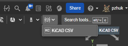
Create new PartStudio and choose the KiCAD SCV script to run.
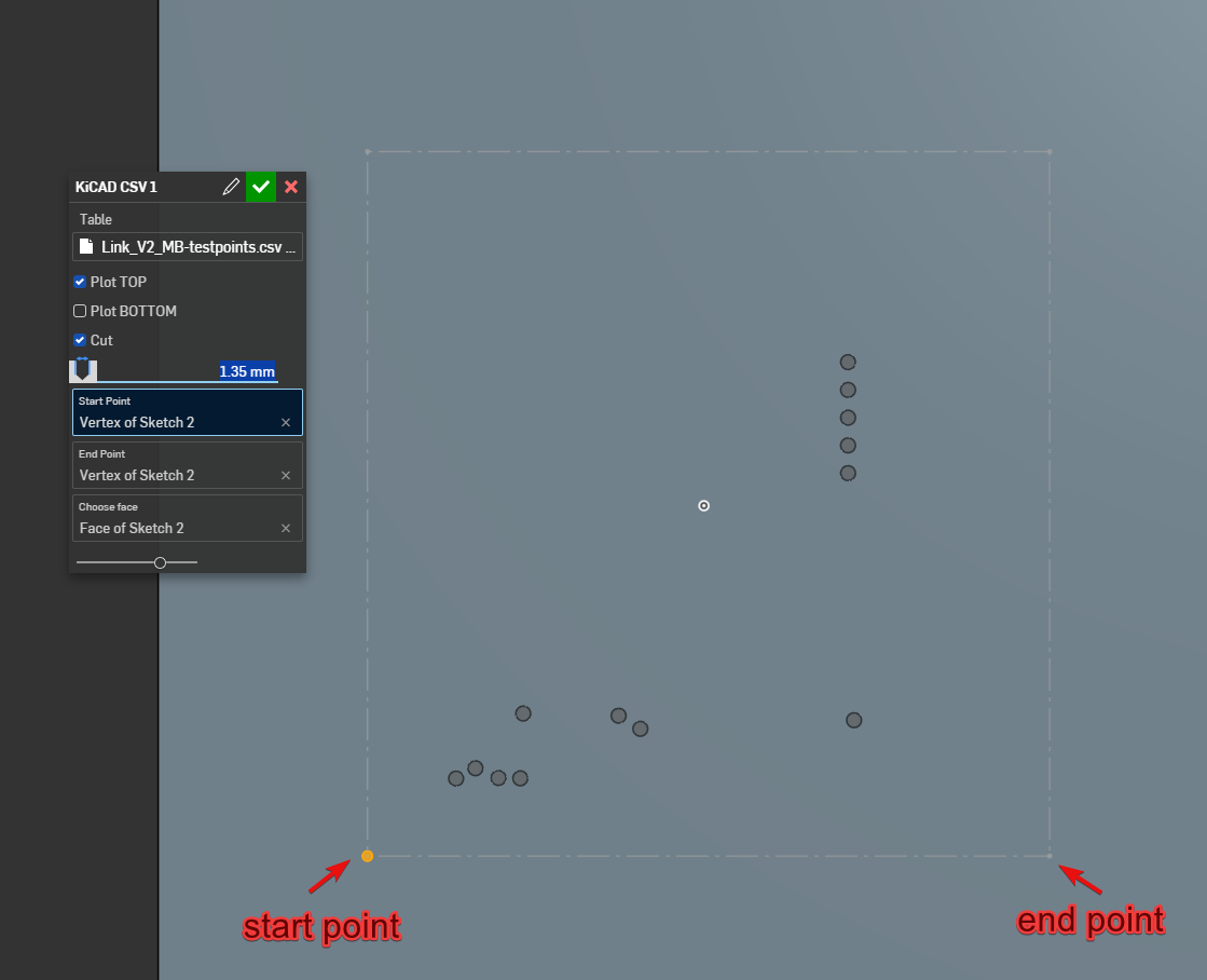
You can choose which side of PCB to use, cut the holes or not. The Two points defines the position of the testpoints
Залишити коментар
Вашу адресу електронної пошти не буде опубліковано. Обов'язкові поля позначені *